Completing the Drop System CAD Assembly
Completing the Drop System CAD Assembly
MECHANICAL | dROPSYSTEM | Date: JUNE 2
MECHANICAL | dROPSYSTEM | Date: JUNE 2


What was accomplished
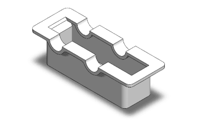
The mechanical department designed the structural foundation and protective enclosures for the motorized winch and tether system. The primary base plate was modeled as the mechanism's structural backbone, featuring a large, centralized aperture for smooth, snag-free tether and payload deployment, surrounded by a precise array of mounting holes. A split-shell gear housing (top and bottom holder) was also designed to fully enclose the custom helical gears, protecting the transmission while maintaining precise spatial positioning.
With those components in place, the department reached a major milestone: the complete digital CAD assembly of the Drop System. All individually modeled components were brought together into a single sub-assembly — the base plate, top and bottom gear housings, helical gear train, zero-slip hexagonal tether spool, and servo motor coupling bracket — confirming that the spatial packaging is optimal and all mechanical pathways align as engineered.
Challenges and solutions
A major challenge in designing the multi-part gear housing was ensuring absolute alignment — even slight misalignment between the top and bottom holders when bolted down would compress the gear shafts and induce friction that could bind or stall the winch under load. The base plate was used as a structural datum reference, with its mounting holes mapped to correspond precisely with both housings, so the bolting process forces all components into self-correcting alignment.
During final assembly, ensuring absolute dynamic clearance was critical, since CAD environments make it easy to inadvertently create part intersections that would be physically impossible to manufacture or operate. An interference detection analysis was run across the sub-assembly, checking tolerances between the rotating components (gears and spool) and the static structural components (housings and base plate). A few microscopic overlaps were identified and resolved by fine-tuning the internal washer dimensions, ensuring smooth operation without internal binding.
Next Steps Plan
With the Drop System sub-assembly fully verified and finalized, focus will shift to system integration — designing the custom mechanical adapters, brackets, and interface points required to securely mount the Drop System sub-assembly onto the main quadcopter airframe.
What was accomplished
The mechanical department designed the structural foundation and protective enclosures for the motorized winch and tether system. The primary base plate was modeled as the mechanism's structural backbone, featuring a large, centralized aperture for smooth, snag-free tether and payload deployment, surrounded by a precise array of mounting holes. A split-shell gear housing (top and bottom holder) was also designed to fully enclose the custom helical gears, protecting the transmission while maintaining precise spatial positioning.
With those components in place, the department reached a major milestone: the complete digital CAD assembly of the Drop System. All individually modeled components were brought together into a single sub-assembly — the base plate, top and bottom gear housings, helical gear train, zero-slip hexagonal tether spool, and servo motor coupling bracket — confirming that the spatial packaging is optimal and all mechanical pathways align as engineered.
Challenges and solutions
A major challenge in designing the multi-part gear housing was ensuring absolute alignment — even slight misalignment between the top and bottom holders when bolted down would compress the gear shafts and induce friction that could bind or stall the winch under load. The base plate was used as a structural datum reference, with its mounting holes mapped to correspond precisely with both housings, so the bolting process forces all components into self-correcting alignment.
During final assembly, ensuring absolute dynamic clearance was critical, since CAD environments make it easy to inadvertently create part intersections that would be physically impossible to manufacture or operate. An interference detection analysis was run across the sub-assembly, checking tolerances between the rotating components (gears and spool) and the static structural components (housings and base plate). A few microscopic overlaps were identified and resolved by fine-tuning the internal washer dimensions, ensuring smooth operation without internal binding.
Next Steps Plan
With the Drop System sub-assembly fully verified and finalized, focus will shift to system integration — designing the custom mechanical adapters, brackets, and interface points required to securely mount the Drop System sub-assembly onto the main quadcopter airframe.

DRAG Tactical Team
ENGINEER | NAVIGATE | DOMINATE
Quick Links
DRAG Tactical Team
King Abdulaziz university
Saudi Arabia
⌖ View on Maps
Visit Us
Quick Links
Quick Links
Visit Us
DRAG Tactical Team
King Abdulaziz university
Saudi Arabia
⌖ View on Maps
DRAG Tactical Team
King Abdulaziz university
Saudi Arabia
⌖ View on Maps
DRAG Tactical Team
King Abdulaziz university
Saudi Arabia
⌖ View on Maps