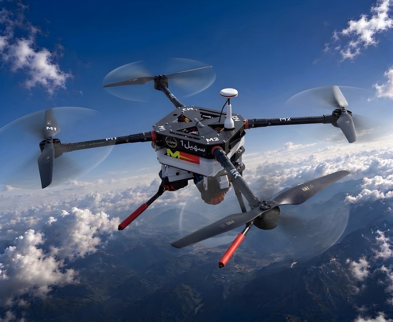
Suhail drone in flight above clouds

SUHAIL

SUHAIL

DESIGNED, MANUFACTURED AND ASSEMBLED IN SAUDI ARABIA.

UAV Performance

SUHIL TESTED PERFORMANCE

SUHIL TESTED PERFORMANCE

+0min
Practical Flight Time
0m/s
Tested Maximum Speed
0.0x
Thrust-to-Weight Ratio
+0Km
Communication Range
+0min
Practical Flight Time
0m/s
Tested Maximum Speed
0.0x
Thrust-to-Weight Ratio
+0Km
Communication Range

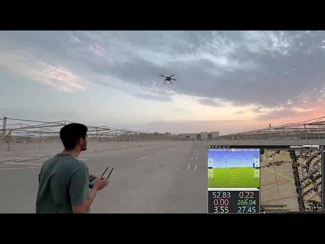
THE VIDEO / 00

THE VIDEO / 00

FLIGHT READINESS PROOF

FLIGHT READINESS PROOF

VALIDATION / 01

VALIDATION / 01

CAD DEVELOPMENT

CAD DEVELOPMENT

The CAD model defined the airframe geometry, payload bay placement, electronics layout, and mounting points before fabrication. This step helped the team validate structure, fit, and serviceability early.

The CAD model defined the airframe geometry, payload bay placement, electronics layout, and mounting points before fabrication. This step helped the team validate structure, fit, and serviceability early.

SYSTEM OVERVIEW / 02

SYSTEM OVERVIEW / 02

SUHAIL TACTICAL INTELLIGENCE PLATFORM

SUHAIL TACTICAL INTELLIGENCE PLATFORM

MISSION VALIDATION

MISSION VALIDATION

Mission testing verified how the aircraft, communication links, camera feed, and payload workflow performed together outside the lab.

Mission testing verified how the aircraft, communication links, camera feed, and payload workflow performed together outside the lab.

DEVELOPMENT / 03

DEVELOPMENT / 03

DEVELOPMENT PROCESS

DEVELOPMENT PROCESS

DEVELOPMENT FOCUS

Flexible airframe

A fallback quadrotor structure kept testing active while the final carbon-frame configuration was refined.

A fallback quadrotor structure kept testing active while the final carbon-frame configuration was refined.

AI and mapping

YOLO-based detection and route mapping were tested together to support autonomous mission decisions.

YOLO-based detection and route mapping were tested together to support autonomous mission decisions.

Portability

Detachable arms and modular assemblies support packing, transport, field repairs, and fast redeployment.

Detachable arms and modular assemblies support packing, transport, field repairs, and fast redeployment.

Airdrop reliability

The release mechanism was simplified to reduce weight while improving timing accuracy and drop consistency.

The release mechanism was simplified to reduce weight while improving timing accuracy and drop consistency.

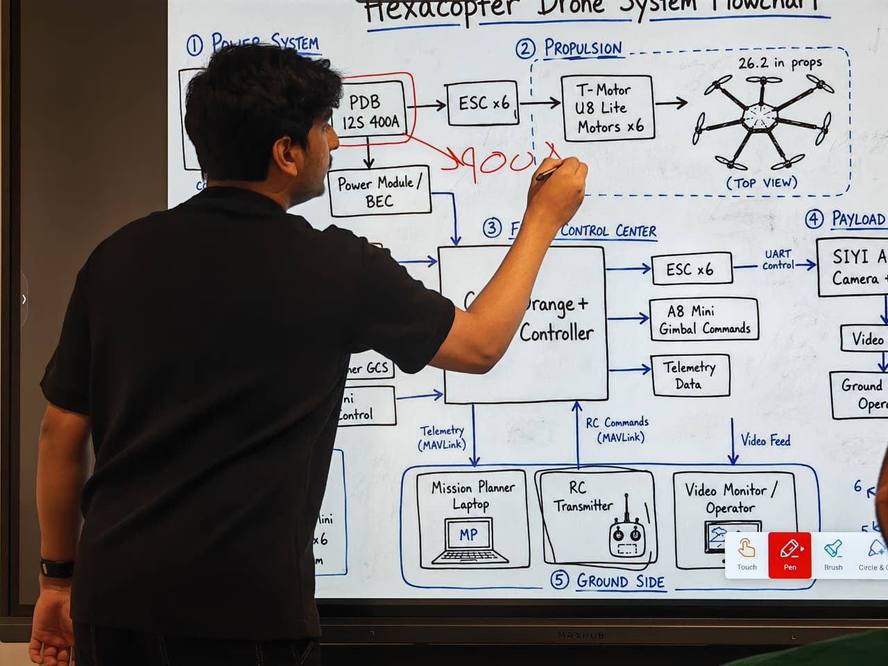
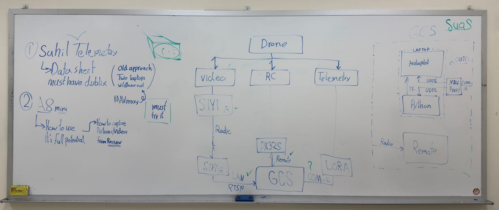
During the development phase, we started by analyzing the overall system architecture and identifying the main components and communication links. We studied how the video stream, RC control, telemetry, and Ground Control Station (GCS) would interact, then evaluated different hardware, communication protocols, and connection methods to determine the most reliable and efficient system configuration.

During the development phase, we started by analyzing the overall system architecture and identifying the main components and communication links. We studied how the video stream, RC control, telemetry, and Ground Control Station (GCS) would interact, then evaluated different hardware, communication protocols, and connection methods to determine the most reliable and efficient system configuration.

BUILD INTEGRATION / 04

BUILD INTEGRATION / 04

MECHANICAL & ELECTRICAL INTEGRATION

MECHANICAL & ELECTRICAL INTEGRATION

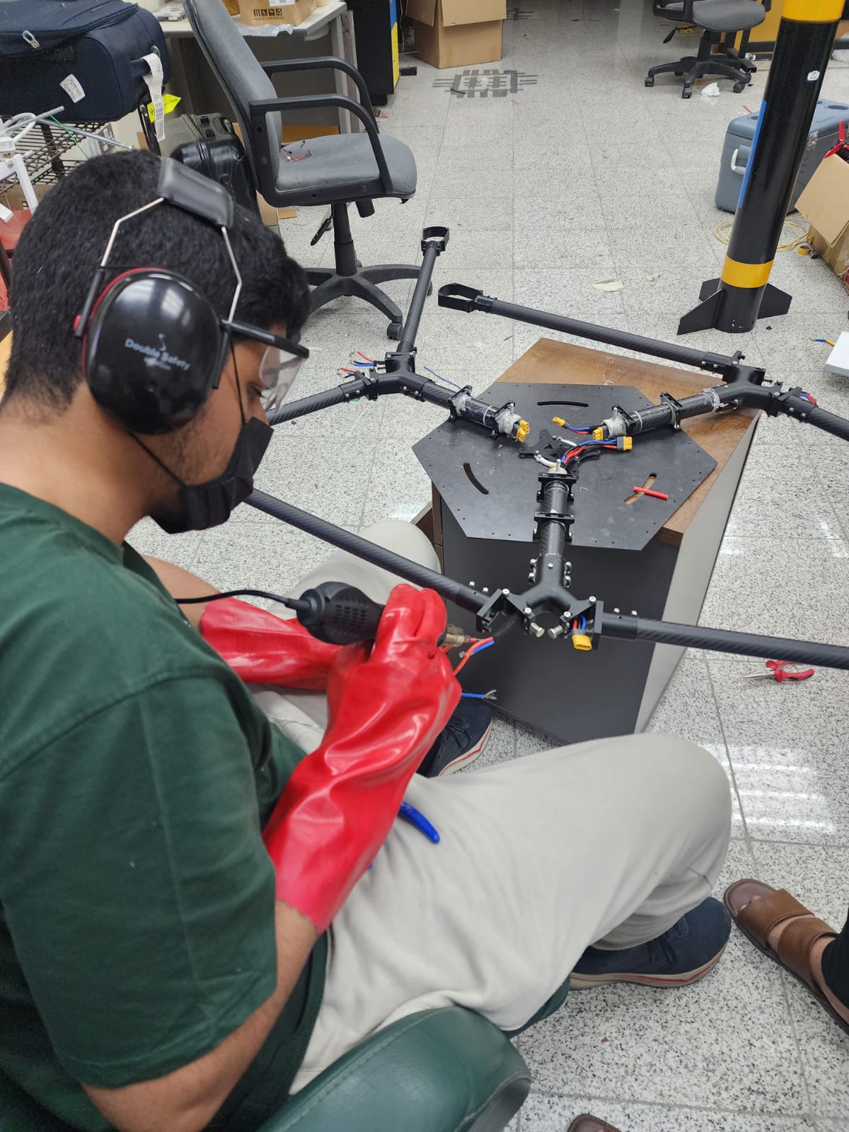
A complete airframe integration section covering the carbon structure, propulsion layout, battery system, wiring, electronics bay, and payload-ready assembly.

A complete airframe integration section covering the carbon structure, propulsion layout, battery system, wiring, electronics bay, and payload-ready assembly.

MECHANICAL & ELECTRICAL INTEGRATION

Mechanical frame

Carbon-fiber tubes, custom 3D-printed joints, detachable arms, reinforced mounts, and a central payload/electronics bay.

Carbon-fiber tubes, custom 3D-printed joints, detachable arms, reinforced mounts, and a central payload/electronics bay.

Electrical system

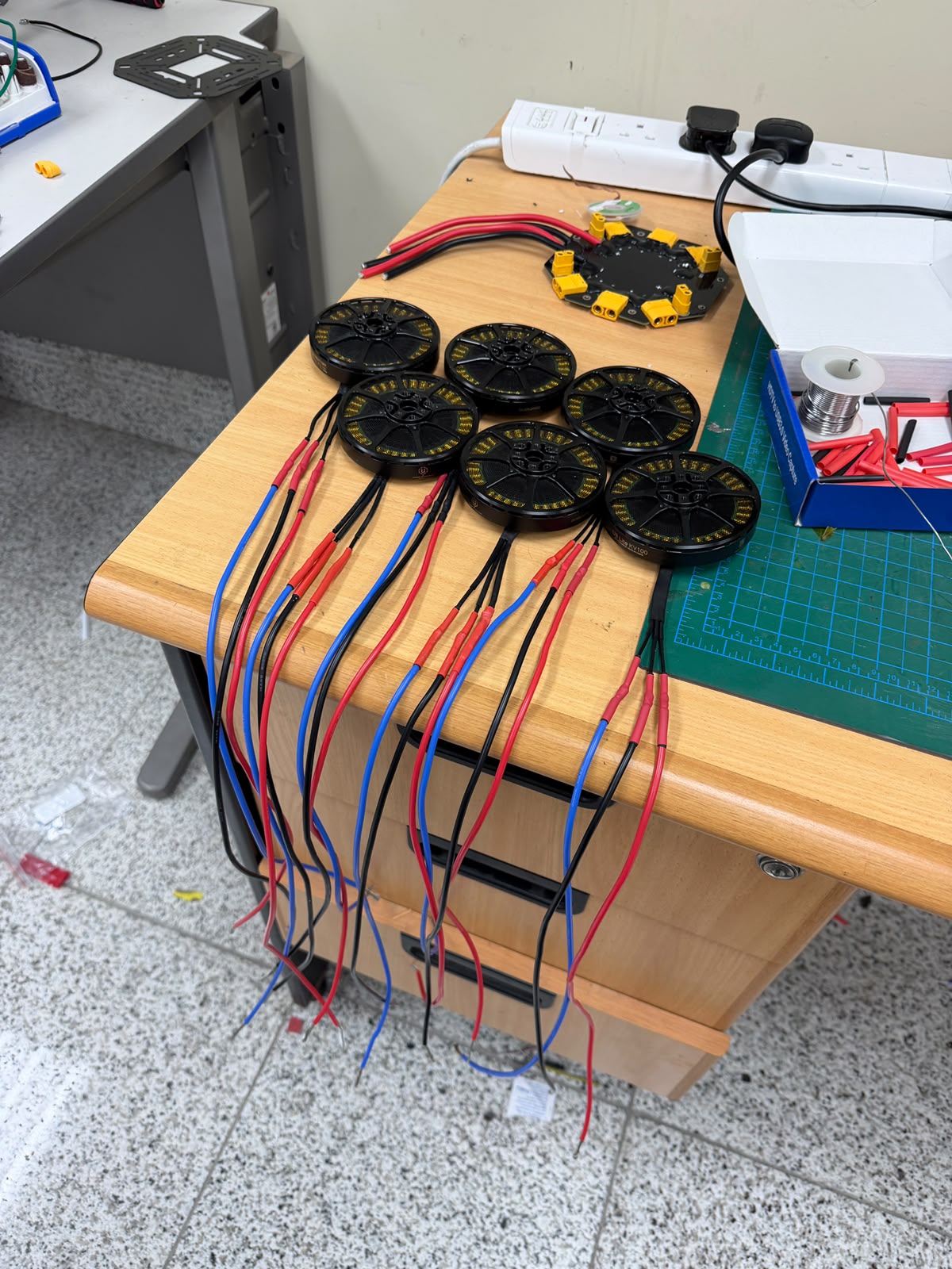
High-capacity battery packs, protected power wiring, ESC connections, distribution planning, and secured routing for field use.

High-capacity battery packs, protected power wiring, ESC connections, distribution planning, and secured routing for field use.

Integration

Components were positioned to improve balance, cooling, maintenance access, structural reliability, and flight readiness.

Components were positioned to improve balance, cooling, maintenance access, structural reliability, and flight readiness.

The integration process began in SolidWorks, where the frame geometry, and electronics mounting points were defined. Simulation and assembly checks helped confirm that the mechanical structure and electrical system could operate together safely before final fabrication, wiring, and flight testing.

PAYLOAD RELEASE / 05

PAYLOAD RELEASE / 05

DROP SYSTEM DESIGN

DROP SYSTEM DESIGN

A controlled four-bay payload system designed to release mission items accurately, gradually, and safely.

A controlled four-bay payload system designed to release mission items accurately, gradually, and safely.

DROP SYSTEM ARCHITECTURE

Payload bays

independent release units allow payloads to be deployed separately.

independent release units allow payloads to be deployed separately.

Mechanism

High-torque servos operate angled gear-reduction mechanisms for controlled movement.

High-torque servos operate angled gear-reduction mechanisms for controlled movement.

Materials

Lightweight PLA components are integrated into the carbon-frame structure.

Lightweight PLA components are integrated into the carbon-frame structure.

Control

Releases can be activated through AI detection, GPS waypoint commands, or manual confirmation from the Ground Control Station.

Releases can be activated through AI detection, GPS waypoint commands, or manual confirmation from the Ground Control Station.

The payload system uses independent bays driven by a high-torque servo and staged gear-reduction mechanism. Releases can be triggered by AI detection with timing controlled over several seconds per item.

AI AND MAPPING / 06

AI AND MAPPING / 06

AI SYSTEM & 2D MAPPING

AI SYSTEM & 2D MAPPING

Computer vision and mapping tools convert flight footage into mission decisions, target markers, and validation data.

Computer vision and mapping tools convert flight footage into mission decisions, target markers, and validation data.

DETECTION AND MISSION LOGIC

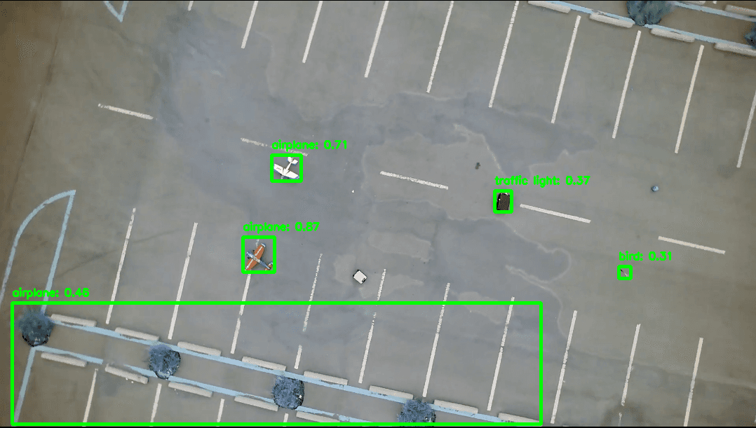
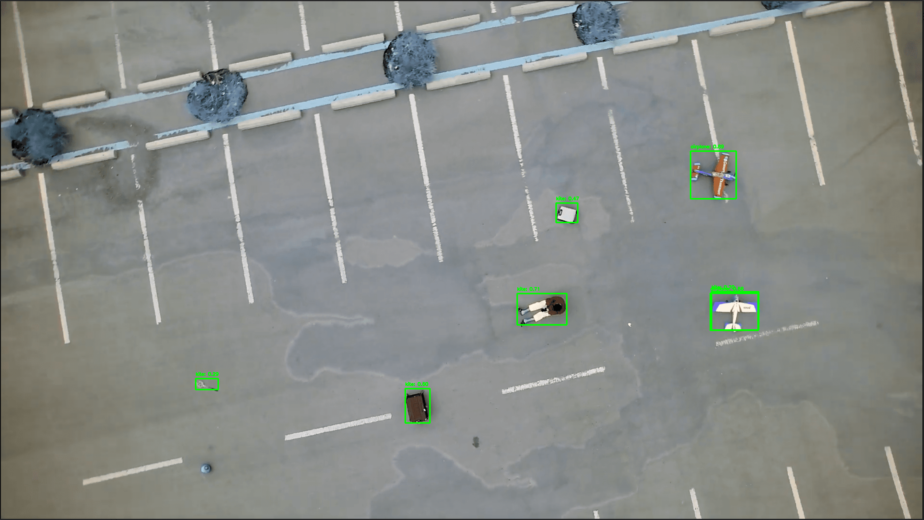
Our onboard AI system transforms aerial footage into actionable mission intelligence. A custom-trained detection model identifies mission-relevant targets such as vehicles, structures, symbols, and markers, then supports payload decisions, route verification, and mission validation from altitude.

DEVELOPMENT FOCUS

Detection engine

A custom-trained model analyzes live and recorded aerial footage for mission targets.

A custom-trained model analyzes live and recorded aerial footage for mission targets.

Mapping pipeline

Detected objects are linked to their estimated geographic positions to create a mission-ready 2D map.

Detected objects are linked to their estimated geographic positions to create a mission-ready 2D map.

Confidence filtering

Low-confidence detections are removed to reduce false results.

Low-confidence detections are removed to reduce false results.

MAVLink integration

Detection data is transmitted to the autopilot and Ground Control Station for display, verification, and mission logging.

Detection data is transmitted to the autopilot and Ground Control Station for display, verification, and mission logging.

GROUND CONTROL / 07

GROUND CONTROL / 07

GROUND CONTROL STATION

GROUND CONTROL STATION

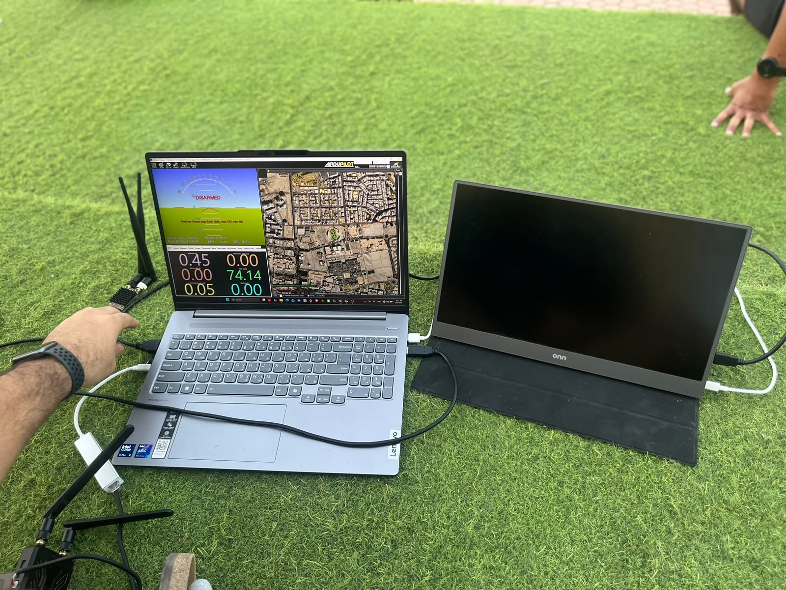
The software combines flight control, waypoint planning, map visualization, live camera streaming, AI object detection, and camera recording control within a single Python interface. This reduces the need for separate applications and allows the operator to manage the entire autonomous mission from one Ground Control Station.

ALL-IN-ONE MISSION SOFTWARE

Live camera feed

Receives and displays the UAV video stream directly inside the software.

Receives and displays the UAV video stream directly inside the software.

Mission planning

Operators place waypoints on the map and draw the complete autonomous flight route.

Operators place waypoints on the map and draw the complete autonomous flight route.

2D mapping

Displays the aircraft position, mission path, target locations, and mapped flight area.

Displays the aircraft position, mission path, target locations, and mapped flight area.

AI detection

Shows detected objects on the live camera feed and records their mission data.

Shows detected objects on the live camera feed and records their mission data.

Camera control

Starts and stops onboard camera recording remotely from the interface.

Starts and stops onboard camera recording remotely from the interface.

Flight telemetry

Monitors GPS position, altitude, speed, heading, battery status, and flight mode.

Monitors GPS position, altitude, speed, heading, battery status, and flight mode.

MAVLink communication

Exchanges commands and mission data with the flight controller.

Exchanges commands and mission data with the flight controller.

Mission execution

Uploads, starts, pauses, updates, and clears waypoint missions.

Uploads, starts, pauses, updates, and clears waypoint missions.

FLIGHT READINESS / CONTROLLED RISK
Safety & Redundancy Protocols

Safety & Redundancy Protocols

BE A SAFETY PILOT
This page doesn't exist — but the drone is still flying.
Space · ↑ · Click · Tap — to flap

DRAG Tactical Team

ENGINEER | NAVIGATE | DOMINATE

Quick Links


DRAG Tactical Team

King Abdulaziz university

Saudi Arabia


⌖ View on Maps

Visit Us


Quick Links

Quick Links


Visit Us

DRAG Tactical Team

King Abdulaziz university

Saudi Arabia


⌖ View on Maps

DRAG Tactical Team

King Abdulaziz university

Saudi Arabia


⌖ View on Maps

DRAG Tactical Team

King Abdulaziz university

Saudi Arabia


⌖ View on Maps

Tactical DRAG Team

ENGINEER | NAVIGATE | DOMINATE

Visit Us


DRAG Tactical Team

King Abdulaziz university

Saudi Arabia

⌖ View on Maps