Mechanical logs
Mechanical logs
MECHANICAL | dROPSYSTEM | Date: MAY 19
MECHANICAL | dROPSYSTEM | Date: MAY 19


What was accomplished
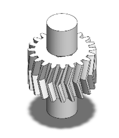
With the conceptual phase complete, the mechanical department moved into detailed CAD modeling of the motorized winch and tether system. Work began with the power transmission mechanism — a custom helical gear train, chosen over standard spur gears for smoother engagement, reduced vibration, and higher load-carrying capacity. Both the driving pinion and driven gear were modeled in SolidWorks.
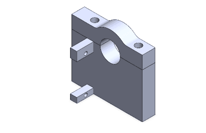
The department then designed the custom spool that winds and deploys the high-strength fishing line, along with a mounting bracket and coupling interface connecting the primary gear shaft to the servo motor. With these pieces finalized, the mechanical pathway is complete: the servo drives the primary gear via the custom mount, which rotates the driven gear, which in turn rotates the spool.
Challenges and solutions
Sizing the gear train was a key challenge — it needed to stay compact enough for the lower deck's limited clearance while balancing servo torque against descent speed, resolved through iterative CAD adjustments to pitch and module. A related issue surfaced during analysis: the helical gears' natural axial thrust was creating side-friction and parasitic drag, slowing deployment. This means the upcoming gear holder must use precise tolerances and thrust-absorbing elements (like washers) to mitigate it.
A further challenge was interfacing the off-the-shelf servo with the custom gear train without introducing backlash — any misalignment between the servo shaft and gear shaft causes binding and limits lifting capacity. The custom mounting bracket was engineered as a rigid alignment block to keep both shafts concentric, and the spool was given a precision hexagonal hub keying into the driven gear's hex shaft to guarantee full torque transfer under load.
Next Steps Plan
Before moving into final CAD assembly, the remaining structural elements need to be designed: the protective housing for the gear train, an accurate CAD representation of the servo motor for documentation, and the main structural base plate serving as the foundation for the mechanism.
What was accomplished
With the conceptual phase complete, the mechanical department moved into detailed CAD modeling of the motorized winch and tether system. Work began with the power transmission mechanism — a custom helical gear train, chosen over standard spur gears for smoother engagement, reduced vibration, and higher load-carrying capacity. Both the driving pinion and driven gear were modeled in SolidWorks.
The department then designed the custom spool that winds and deploys the high-strength fishing line, along with a mounting bracket and coupling interface connecting the primary gear shaft to the servo motor. With these pieces finalized, the mechanical pathway is complete: the servo drives the primary gear via the custom mount, which rotates the driven gear, which in turn rotates the spool.
Challenges and solutions
Sizing the gear train was a key challenge — it needed to stay compact enough for the lower deck's limited clearance while balancing servo torque against descent speed, resolved through iterative CAD adjustments to pitch and module. A related issue surfaced during analysis: the helical gears' natural axial thrust was creating side-friction and parasitic drag, slowing deployment. This means the upcoming gear holder must use precise tolerances and thrust-absorbing elements (like washers) to mitigate it.
A further challenge was interfacing the off-the-shelf servo with the custom gear train without introducing backlash — any misalignment between the servo shaft and gear shaft causes binding and limits lifting capacity. The custom mounting bracket was engineered as a rigid alignment block to keep both shafts concentric, and the spool was given a precision hexagonal hub keying into the driven gear's hex shaft to guarantee full torque transfer under load.
Next Steps Plan
Before moving into final CAD assembly, the remaining structural elements need to be designed: the protective housing for the gear train, an accurate CAD representation of the servo motor for documentation, and the main structural base plate serving as the foundation for the mechanism.

DRAG Tactical Team
ENGINEER | NAVIGATE | DOMINATE
Quick Links
DRAG Tactical Team
King Abdulaziz university
Saudi Arabia
⌖ View on Maps
Visit Us
Quick Links
Quick Links
Visit Us
DRAG Tactical Team
King Abdulaziz university
Saudi Arabia
⌖ View on Maps
DRAG Tactical Team
King Abdulaziz university
Saudi Arabia
⌖ View on Maps
DRAG Tactical Team
King Abdulaziz university
Saudi Arabia
⌖ View on Maps