Structural and Vibration Analysis of the Quadcopter Arm
Structural and Vibration Analysis of the Quadcopter Arm
MECHANICAL | FRAME | Date: JUNE 30
MECHANICAL | FRAME | Date: JUNE 30


What was accomplished
The mechanical department ran a full structural verification of the quadcopter arm assembly in SOLIDWORKS Simulation, covering both a modal (frequency) study and a static structural study.
For the modal study, the team fixed the arm at its clamp interfaces and modeled the motor and propeller as a 400g remote mass, with the CFRP arm treated as equivalent isotropic material. Excitation data came from T-Motor's own bench test results for the U8 Lite KV100 motor paired with a 28×9.2 in propeller, across its normal operating range of 1896–3709 RPM. The team found the arm's first bending mode at 65.953 Hz, with a second mode just above it at 66.8 Hz forming an orthogonal first-bending pair, and three higher modes (435.8, 689.0, and 706.2 Hz) sitting well above the propeller's excitation range.
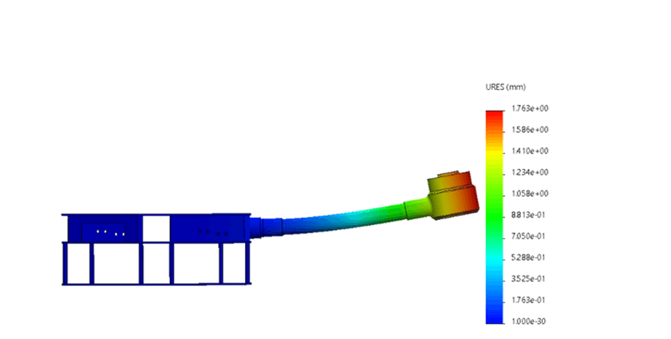
The team then ran a static structural study, loading one arm with the rest of the frame's arm interfaces held fixed — a deliberately conservative setup compared to real free flight. A 103 N load was applied at the motor mount, matching the motor's maximum static thrust with a 1.2 safety margin built in, along with the matching 2.73 N·m rotor torque. This returned a peak stress of 42.5 MPa and a maximum tip deflection of 1.76 mm.
Challenges and solutions
The main question going into the modal study was whether the arm's first bending mode would land on top of the propeller's blade-passing frequency during flight — a classic resonance risk. The team found that the two do cross, but only at 1980 RPM, safely below the drone's 2270 RPM hover speed, giving about 13% separation once actually hovering. Since the crossing happens below hover rather than at it, and flight testing showed no sustained vibration, the team concluded this isn't a real resonance concern in normal operation. To make sure this result wasn't just a modeling fluke, frequencies were re-checked across different mesh densities and bonding tolerances, and stayed within 5% each time — confirming the result holds up. The study also flagged the stepped tube splice as the part of the arm doing the most to limit its stiffness, so the team is now recommending a switch to a single uniform tube going forward.
For the static study, the key question was whether raw strength would be the limiting factor in the design. Comparing the 42.5 MPa peak stress against the material limits — 600 MPa for the carbon fiber tube and 275 MPa for the 6061-T6 aluminum fittings — gave large safety margins of 13.1 and 5.5 respectively. That confirmed strength isn't actually the bottleneck for this frame; how stiff and how vibration-resistant it is matters far more, which lines up with what the modal study already showed.
Next Steps Plan
Once the carbon fiber tubes, plates, and mounting hardware are delivered, the plan is to precision-cut the arms to their calculated lengths and begin dry assembly of the central chassis plates using the newly machined aluminum standoffs.
What was accomplished
The mechanical department ran a full structural verification of the quadcopter arm assembly in SOLIDWORKS Simulation, covering both a modal (frequency) study and a static structural study.
For the modal study, the team fixed the arm at its clamp interfaces and modeled the motor and propeller as a 400g remote mass, with the CFRP arm treated as equivalent isotropic material. Excitation data came from T-Motor's own bench test results for the U8 Lite KV100 motor paired with a 28×9.2 in propeller, across its normal operating range of 1896–3709 RPM. The team found the arm's first bending mode at 65.953 Hz, with a second mode just above it at 66.8 Hz forming an orthogonal first-bending pair, and three higher modes (435.8, 689.0, and 706.2 Hz) sitting well above the propeller's excitation range.
The team then ran a static structural study, loading one arm with the rest of the frame's arm interfaces held fixed — a deliberately conservative setup compared to real free flight. A 103 N load was applied at the motor mount, matching the motor's maximum static thrust with a 1.2 safety margin built in, along with the matching 2.73 N·m rotor torque. This returned a peak stress of 42.5 MPa and a maximum tip deflection of 1.76 mm.
Challenges and solutions
The main question going into the modal study was whether the arm's first bending mode would land on top of the propeller's blade-passing frequency during flight — a classic resonance risk. The team found that the two do cross, but only at 1980 RPM, safely below the drone's 2270 RPM hover speed, giving about 13% separation once actually hovering. Since the crossing happens below hover rather than at it, and flight testing showed no sustained vibration, the team concluded this isn't a real resonance concern in normal operation. To make sure this result wasn't just a modeling fluke, frequencies were re-checked across different mesh densities and bonding tolerances, and stayed within 5% each time — confirming the result holds up. The study also flagged the stepped tube splice as the part of the arm doing the most to limit its stiffness, so the team is now recommending a switch to a single uniform tube going forward.
For the static study, the key question was whether raw strength would be the limiting factor in the design. Comparing the 42.5 MPa peak stress against the material limits — 600 MPa for the carbon fiber tube and 275 MPa for the 6061-T6 aluminum fittings — gave large safety margins of 13.1 and 5.5 respectively. That confirmed strength isn't actually the bottleneck for this frame; how stiff and how vibration-resistant it is matters far more, which lines up with what the modal study already showed.
Next Steps Plan
Once the carbon fiber tubes, plates, and mounting hardware are delivered, the plan is to precision-cut the arms to their calculated lengths and begin dry assembly of the central chassis plates using the newly machined aluminum standoffs.

DRAG Tactical Team
ENGINEER | NAVIGATE | DOMINATE
Quick Links
DRAG Tactical Team
King Abdulaziz university
Saudi Arabia
⌖ View on Maps
Visit Us
Quick Links
Quick Links
Visit Us
DRAG Tactical Team
King Abdulaziz university
Saudi Arabia
⌖ View on Maps
DRAG Tactical Team
King Abdulaziz university
Saudi Arabia
⌖ View on Maps
DRAG Tactical Team
King Abdulaziz university
Saudi Arabia
⌖ View on Maps